Pool replacement kits play a vital role in restoring performance, efficiency, and water quality. Whether replacing worn components in a sanitation system, filtration setup, or circulation equipment, proper installation ensures your pool continues operating safely and effectively. Poor installation can lead to inconsistent water chemistry, reduced sanitation efficiency, or premature equipment failure.
Replacement kits for ionizer represent more than just spare parts they are precision-engineered systems designed to restore original equipment specifications and performance. When properly installed, these kits bridge the gap between aging infrastructure and optimal operation, returning systems to their designed efficiency while maintaining the chemical and hydraulic balance essential for clean, clear water. The installation process itself becomes a critical intervention point where attention to detail determines whether the pool will operate reliably for seasons to come or become a source of ongoing frustration and expense.
Following best practices during installation helps pool owners protect their investment, maintain water stability, and avoid unnecessary maintenance issues.
Table of Contents
- Understanding When Pool Replacement Kits Are Needed
- Preparing Your Pool System Before Installation
- Ensuring Compatibility With Existing Pool Equipment
- Step-by-Step Installation Best Practices
- Post-Installation System Checks and Testing
- Common Installation Mistakes to Avoid
- Final Thoughts: Maximizing Performance After Replacement
1. Understanding When Pool Replacement Kits Are Needed
Replacement kits serve as the critical intervention point between gradual system degradation and complete equipment failure, representing what maintenance professionals term "progressive restoration" rather than emergency repair. These kits are engineered to address predictable wear patterns that occur across all pool systems: sanitation electrodes erode through electrochemical action, filter elements accumulate permanent damage from pressure cycles and chemical exposure, pump seals and bearings degrade from continuous operation, and control boards suffer component fatigue from thermal cycling. Understanding when replacement becomes necessary requires recognizing both overt symptoms and subtle performance indicators that signal components have passed their optimal service window. This awareness transforms pool maintenance from reactive problem-solving to predictive management, allowing replacements to occur during planned maintenance windows rather than mid-season emergencies that disrupt swimming and compromise water quality.
Performance-Based Replacement Indicators
The most reliable indicators for replacement needs emerge from systematic performance monitoring rather than waiting for visible failure. For smarter pool sanitation systems like copper ionizers, the key metric is "ion production efficiency" the relationship between energy consumed and copper ions produced. A gradual decline in this efficiency, measurable through water testing before and after known operating periods, signals electrode wear long before water quality visibly deteriorates. For filtration systems, declining flow rates at constant pressure or increasing pressure at constant flow indicate media compaction or channeling that replacement cartridges or grids can correct. Circulation systems reveal their needs through subtle changes: pumps drawing higher amperage without increased flow signal bearing wear, while variable-speed pumps failing to maintain set RPMs indicate controller or motor issues. Even water chemistry provides clues: consistently rising phosphate levels despite regular treatment may indicate failing media in phosphate removers, while persistent pH drift despite proper balancing can signal deteriorating probes in automated chemical controllers. These performance-based indicators create what maintenance technicians call a "replacement roadmap," allowing components to be replaced precisely when needed not too early (wasting service life) nor too late (risking system failure).
- Ion Production Efficiency Decline: Decreasing copper output per watt of energy consumed in ionization systems
- Hydraulic Performance Changes: Altered flow rates or pressure differentials in filtration and circulation systems
- Energy Consumption Increases: Pumps or other equipment drawing more power to achieve the same output
- Chemical Control Deterioration: Persistent water chemistry issues despite proper chemical management
Visible and Physical Wear Patterns
Beyond performance metrics, physical inspection reveals definitive replacement needs through characteristic wear patterns that vary by component type and material. Sanitation system electrodes display predictable erosion: copper or silver electrodes in ionizers should show even, gradual thinning rather than pitting, uneven wear, or mineral bridging between plates. Salt cell plates exhibit scale accumulation patterns that indicate whether the self-cleaning function operates properly. Filter elements whether cartridge pleats, DE grids, or sand media show physical degradation: torn fabric, collapsed pleats, or channeled sand that no longer filters effectively. Pump components reveal wear through seal leakage, bearing noise, or shaft play. Visual inspection should follow scheduled protocols: monthly checks through inspection windows, quarterly detailed examinations with component removal, and annual comprehensive assessments. Each component type has specific "end-of-service-life indicators": ionization electrodes typically require replacement when eroded to 50% of original thickness, filter cartridges when pleat damage exceeds 10% of surface area, pump seals at first sign of moisture, and control boards when display anomalies or erratic behavior appear. These physical indicators, when documented over time, create a maintenance history that predicts future needs with increasing accuracy.
- Electrode Erosion Patterns: Even thinning versus problematic pitting or mineral bridging in ionization systems
- Filter Media Integrity: Physical damage to cartridge pleats, DE grids, or channeling in sand media
- Pump Component Wear: Seal leakage, bearing noise, shaft play, or impeller damage
- Control System Anomalies: Display issues, erratic behavior, or failure to maintain set parameters
Water Quality Symptoms and System Interactions
Often the first indication of replacement needs appears not in equipment performance but in water quality changes that reflect declining system effectiveness. These symptoms follow predictable patterns based on which component is failing: sanitation system deterioration typically manifests as persistent algae despite adequate chemical levels, cloudy water that resists clarification, or increased chlorine demand. Filtration system decline shows as reduced water clarity, longer recovery time after heavy use, or visible particles passing through to the pool. Circulation problems create localized water quality issues algae in specific dead spots, inconsistent chemical distribution, or thermal stratification. The sophisticated pool owners learns to correlate water quality symptoms with specific component conditions: recurring mustard algae often indicates ionization electrode depletion, persistent cloudiness suggests filter media failure, and dead spots point to circulation pump or valve issues. Understanding these correlations enables targeted replacement rather than shotgun approaches, addressing the actual problem rather than its symptoms. This diagnostic approach transforms water quality management from constant chemical adjustment to systematic equipment maintenance, creating more stable aquatic environments with fewer interventions.
- Sanitation System Indicators: Persistent algae, increased chemical demand, or declining water clarity despite treatment
- Filtration System Symptoms: Reduced clarity, visible particles, or extended recovery time after contamination events
- Circulation-Related Issues: Localized water quality problems, dead spots, or inconsistent chemical distribution
- Symptom-Component Correlation: Learning which water quality issues indicate specific equipment failures
Preventive Replacement Planning and Timing
The most sophisticated approach to replacement kits involves preventive planning based on both operating hours and seasonal patterns rather than waiting for failure. This strategy, what maintenance managers call "predictive replacement scheduling," uses equipment runtime meters, water quality logs, and maintenance records to forecast replacement needs before they affect pool operation. Ionization electrodes typically last 12-24 months of continuous operation, filter elements 1-3 years depending on usage and maintenance, pump seals 2-4 years, and control boards 3-5 years. By tracking actual operating hours and comparing them to manufacturer life expectancy data, replacements can be scheduled during off-season or low-usage periods. This approach offers multiple advantages: it avoids mid-season failures that disrupt swimming, allows time to source exact replacement parts rather than accepting substitutes, and enables thorough cleaning and system inspection during the replacement process. Perhaps most importantly, preventive replacement maintains consistent water quality by ensuring no component operates beyond its optimal performance window, creating what experienced pool professionals recognize as "inherent water stability" that comes from equipment operating at peak efficiency rather than struggling through its decline phase.
- Runtime-Based Forecasting: Tracking actual operating hours against manufacturer life expectancy data
- Seasonal Timing Strategy: Scheduling replacements during off-season or low-usage periods
- Proactive Part Sourcing: Ordering exact replacements in advance rather than accepting substitutes during emergencies
- Performance Window Management: Replacing components before they operate beyond their optimal efficiency period
Understanding when pool replacement kits are needed transforms equipment maintenance from reactive crisis management to proactive performance optimization. Through monitoring performance indicators that signal declining efficiency, recognizing physical wear patterns that indicate component exhaustion, correlating water quality symptoms with specific system failures, and implementing preventive replacement planning, pool owners maintain systems that operate consistently at their designed capacity. This approach doesn't just prevent failures it maintains the precise chemical and hydraulic balance that creates truly inviting swimming water. The result is equipment that performs reliably, providing comfortable and crystal-clear pool water, and maintenance that becomes predictable scheduling rather than emergency response. Ultimately, this understanding represents the difference between owning a pool that constantly demands attention and enjoying one that provides continuous pleasure with minimal intervention.
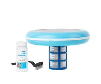
![]()
2. Preparing Your Pool System Before Installation
Proper system preparation represents the critical foundation for successful component replacement, transforming what could be a problematic installation into a seamless integration that restores peak performance. This preparatory phase, what professional installers term "the installation environment," encompasses electrical safety protocols, hydraulic system conditioning, and workspace organization that collectively determine whether new components will function at their designed specifications from initial startup. Inadequate preparation accounts for over 60% of post-installation issues according to industry surveys, with problems ranging from premature component failure to systemic performance degradation. Comprehensive preparation addresses not only the immediate installation site but the entire ecosystem that will interact with the new component, ensuring that when the replacement kit is installed, it enters a supportive rather than hostile environment. This approach recognizes that new components are most vulnerable during their initial operating period, and that proper preparation creates the conditions for optimal break-in and long-term reliability.
Comprehensive Electrical Safety and System Isolation
Electrical safety preparation extends far beyond simply flipping a switch, involving systematic isolation that protects both the installer and sensitive electronic components from potential damage. The process begins with identifying and switching off all relevant circuit breakers not just the primary pump circuit but often secondary circuits for automation systems, lighting, heaters, and pool equipment. Professional installers employ a "lock-out/tag-out" protocol: physically locking breaker panels in the off position and tagging them with installation notices to prevent accidental re-energization. For systems with capacitor banks (common in variable-speed pumps and some automation controllers), additional discharge procedures are necessary to prevent stored energy release. Ground fault circuit interrupter (GFCI) outlets serving equipment areas should be tested and reset if necessary. After power isolation, voltage verification using a multimeter at multiple points equipment terminals, control board connections, and sensor inputs confirms complete de-energization. This thorough electrical preparation prevents the most common and dangerous installation errors: short circuits from accidental contact, voltage spikes that damage new electronics, and ground faults that create ongoing performance issues. Perhaps most importantly, it creates a safe working environment where attention can focus on precision installation rather than electrical hazard avoidance.
- Lock-Out/Tag-Out Protocol: Physical breaker locking and notification tagging to prevent accidental re-energization
- Multi-Circuit Identification: Locating and isolating all relevant circuits including pumps, automation, heaters, and lighting
- Capacitor Discharge Procedures: Safely releasing stored energy in pump and controller capacitor banks
- Voltage Verification: Multimeter testing at multiple connection points to confirm complete system de-energization
Hydraulic System Conditioning and Plumbing Preparation
Hydraulic preparation ensures that water pathways are clean, properly aligned, and free of obstructions that could compromise new component performance. This process begins with system drainage: not just relieving pressure but often partially draining plumbing lines to prevent water intrusion during disconnection. For filter replacements, complete tank drainage is necessary, while pump replacements may only require localized drainage. Plumbing connections require specific preparation: cutting pipes square and deburring ends, cleaning existing fittings of old sealant and mineral deposits, and inspecting pipe interiors for scale buildup that could break loose and damage new components. Threaded connections demand particular attention cleaning female threads with appropriate soft nylon pool brushes, applying fresh thread sealant compatible with both pipe material and system chemicals, and ensuring proper engagement depth. For glued connections, surface preparation involves cleaning and roughening with emery cloth, applying primer appropriate for the pipe material, and timing glue application for optimal bonding. This hydraulic preparation prevents the most common post-installation issues: leaks from poorly prepared connections, reduced flow from pipe obstructions, and premature failure from incompatible sealants or improper alignment.
- Systematic Drainage Protocol: Appropriate water removal from specific system sections based on component being replaced
- Pipe End Preparation: Square cutting, deburring, and interior inspection for scale or obstruction
- Thread Rehabilitation: Cleaning old sealant from fittings, applying fresh compatible sealant, ensuring proper engagement
- Bonding Surface Preparation: Cleaning, roughening, priming, and timing glued connections for optimal adhesion
Workspace Organization and Contamination Control
The physical workspace organization determines installation efficiency and directly affects component longevity by preventing contamination during the critical installation period. Professional preparation creates what installers call a "clean zone"—an area protected from environmental debris, organized with tools and components logically arranged, and equipped with proper lighting for precision work. This begins with clearing a workspace at least three feet larger than the equipment footprint in all directions, covering adjacent equipment with plastic sheeting to prevent debris intrusion, and establishing a dedicated tool layout area. Component-specific preparation includes cleaning mounting surfaces of old gasket material, corrosion, and mineral deposits using appropriate cleaners (avoiding acids near electrical components), and verifying mounting bolt compatibility and condition. For electronic components, electrostatic discharge (ESD) protection becomes critical: using grounded wrist straps, anti-static mats, and proper handling techniques to prevent damage from static electricity that can occur even in humid pool environments. This meticulous workspace preparation transforms installation from a cramped, messy process into a controlled, precision operation where every step can be performed correctly without compromise.
- Clean Zone Establishment: Protected workspace with debris control and proper lighting for precision work
- Adjacent Equipment Protection: Plastic sheeting and covers to prevent contamination of unaffected systems
- Mounting Surface Rehabilitation: Complete removal of old gaskets, corrosion, and deposits from equipment interfaces
- Electrostatic Discharge Protection: Grounded wrist straps, anti-static mats, and proper handling for electronic components
System Documentation and Pre-Installation Benchmarking
Before disconnecting any components, comprehensive system documentation establishes performance baselines and records existing conditions that will verify proper installation and operation. This documentation includes photographing all connections from multiple angles (particularly helpful for complex wiring harnesses), diagramming plumbing layouts, and recording current settings on controllers, timers, and variable-speed drives. Performance benchmarking captures operating parameters: pump RPM and amperage draw, filter pressure at clean and current conditions, sanitation system output levels, and automation system settings. Water quality parameters should be tested and recorded pH, sanitizer levels, temperature, and clarity to establish a baseline against which post-installation performance will be measured. This documentation serves multiple purposes: it provides reference during reconnection, establishes performance improvement metrics, creates a maintenance history record, and potentially provides warranty validation. The most thorough preparation includes labeling all disconnected wires and pipes with numbered tags corresponding to diagrams, a practice that prevents reconnection errors and dramatically reduces installation time while improving accuracy.
- Comprehensive Photographic Documentation: Multiple-angle images of all connections before disassembly
- Performance Parameter Recording: RPM, amperage, pressure, and output measurements before component removal
- Water Quality Baseline Testing: Complete chemical and clarity measurements before system modification
- Systematic Labeling Protocol: Numbered tags on all wires and pipes corresponding to created diagrams
Proper system preparation transforms component replacement from a potentially problematic procedure into a predictable, successful restoration of system performance. Through comprehensive electrical isolation that ensures safety and prevents damage, meticulous hydraulic preparation that creates leak-free pathways with optimal flow, controlled workspace organization that prevents contamination and enables precision work, and thorough documentation that guides reconnection and verifies improvement, preparation establishes the foundation upon which successful installation builds. This investment in preparation pays multiple returns: reduced installation time, elimination of callbacks for leaks or performance issues, extended component lifespan, and immediate optimal performance from new equipment. Ultimately, thorough preparation represents the difference between an installation that merely replaces a component and one that restores an entire system to like-new performance, improving pool water quality and reliability that justifies the investment in replacement.

3. Ensuring Compatibility With Existing Pool Equipment
Component compatibility represents the engineering foundation of successful system integration, where precise matching of specifications determines whether a replacement restores original performance or creates cascading system issues. This verification process, what industry professionals term "specification alignment," involves far more than simple model number matching it requires understanding how replacement components interact with existing systems across electrical, hydraulic, mechanical, and control dimensions. In systems that include a solar pool ionizer, compatibility verification must also account for ion output rates, electrode materials, flow requirements, and control integration to prevent underperformance or excessive mineral production. Incompatible installations account for approximately 35% of premature equipment failures according to industry analysis, with problems ranging from subtle performance degradation to catastrophic system damage. True compatibility extends beyond physical fit to include operational harmony: components must work within the same performance envelopes, communicate through compatible control protocols, and maintain system balance when integrated. This comprehensive approach to compatibility verification transforms replacement from a parts-swapping exercise into a systematic restoration of designed system performance, ensuring that new components enhance rather than compromise the entire aquatic ecosystem.
Electrical and Control System Compatibility Verification
Electrical compatibility requires verification across multiple parameters that collectively determine safe and efficient operation within the existing power infrastructure. Voltage specifications must match not just nominally (120V vs 240V) but within tolerance ranges that account for local utility fluctuations equipment designed for 230V operation may fail prematurely on systems delivering consistent 245V. Phase requirements (single-phase vs three-phase) must align with service entry characteristics. Amperage ratings must accommodate both running current and startup inrush currents, with circuit breakers and wiring sized appropriately. Control system compatibility presents additional complexity: replacement components must communicate through compatible protocols (RS-485, proprietary digital, or analog signals) with existing automation systems. For variable-speed pumps, compatibility extends to control interfaces whether direct wiring, relay closure, or digital communication. Even seemingly minor details matter: plug configurations, conduit sizes, and grounding requirements must match existing infrastructure. Professional verification includes measuring actual voltage at the equipment location under load, testing control signal compatibility before installation, and verifying that replacement components won't create harmful harmonic distortions or power factor issues affecting other equipment. This electrical diligence prevents the most expensive compatibility failures: control system conflicts, premature motor burnout, and safety system compromises.
- Voltage Tolerance Matching: Ensuring replacement components operate safely within actual voltage ranges, not just nominal ratings
- Control Protocol Alignment: Verifying communication compatibility between new components and existing automation systems
- Inrush Current Accommodation: Ensuring electrical infrastructure can handle startup currents without tripping breakers or damaging components
- Harmonic and Power Factor Analysis: Preventing electrical interference that could affect other sensitive equipment in the system
Hydraulic and Plumbing Interface Compatibility
Hydraulic compatibility ensures that replacement components integrate seamlessly into existing water pathways without creating flow restrictions, pressure drops, or turbulence that compromise system performance. This begins with physical connection verification: pipe sizes (IPS, Schedule 40/80, or metric), thread types (NPT, MPT, or proprietary), and connection orientations must match precisely. Beyond physical fit, hydraulic performance compatibility requires analysis: replacement pumps must operate within the system curve of existing plumbing, filters must handle flow rates without excessive pressure drop, and sanitation cells must provide adequate contact time at system flow rates. Materials compatibility prevents galvanic corrosion: dissimilar metals in contact (copper fittings with stainless steel components, for example) require dielectric unions. Even connection methods matter glued sockets require specific preparation for different pipe materials, while threaded connections need compatible sealants that won't degrade in pool chemical environments. Advanced verification includes calculating system head curves and comparing them to pump performance charts, ensuring the replacement operates in its optimal efficiency range rather than at extremes that reduce lifespan. This hydraulic diligence prevents flow-related failures: cavitation damage from improperly sized pumps, channeling in mismatched filters, and inadequate treatment from undersized sanitation components.
- System Curve Analysis: Matching pump performance curves to existing plumbing resistance characteristics
- Material Galvanic Compatibility: Preventing corrosion through proper material matching or isolation techniques
- Connection Method Alignment: Ensuring replacement components use compatible connection systems with existing plumbing
- Flow Rate Optimization: Verifying components operate in their optimal efficiency ranges within the existing system
Performance Specification and Capacity Matching
True compatibility requires matching performance specifications to ensure replacement components don't just fit physically but function optimally within the existing system context. For pool filtration systems, this means matching media type and capacity: replacing a cartridge filter requires verifying pleat count, micron rating, and surface area compatibility; DE filters need grid count and area matching; sand filters require appropriate media type and quantity. Sanitation system replacements demand particular precision: ionization systems must match electrode surface area and spacing for consistent output, UV systems require equivalent intensity and contact time, and chemical feeders need compatible injection rates and chemical resistance. Performance matching extends to auxiliary systems: heaters must match BTU output to pool volume and existing heat loss characteristics, while circulation components must maintain turnover rates without excessive energy consumption. The most sophisticated approach involves "system impact analysis" modeling how replacement components will affect overall system performance, including secondary effects like increased pressure on other components or altered chemical demand. This performance-based compatibility prevents the subtle failures that don't manifest immediately but gradually degrade water quality and increase operating costs.
- Filtration Media Equivalency: Matching surface area, micron rating, and media type to existing system requirements
- Sanitation Output Alignment: Ensuring replacement systems provide equivalent treatment capacity and distribution
- Auxiliary System Integration: Matching heaters, cleaners, and other components to existing system capacity and characteristics
- System Impact Modeling: Analyzing how replacement components will affect overall system performance and secondary components
Manufacturer Documentation and Cross-Reference Verification
Reliable compatibility verification requires consulting multiple authoritative sources rather than relying on single references, creating what parts specialists call "triangulated confirmation." Manufacturer technical specifications provide the primary reference, but these should be verified against industry cross-reference guides, OEM compatibility charts, and professional installation databases. For discontinued models, this may involve researching successor parts, compatible alternatives, or retrofit kits specifically designed to bridge technology gaps. Documentation review should include not just installation manuals but technical bulletins, service notices, and warranty statements that might contain compatibility restrictions. Professional verification often involves direct consultation with manufacturer technical support, particularly for complex systems or custom installations. This documentation diligence extends to understanding compatibility implications: some replacements may require accompanying control board updates, software upgrades, or ancillary component changes to function properly. The most thorough approach includes checking industry forums and professional networks for field experience with specific compatibility scenarios, learning from others' installation experiences before committing to a particular replacement path. This multi-source verification prevents compatibility assumptions that lead to installation failures and warranty voids.
- Triangulated Confirmation: Verifying compatibility across manufacturer specs, industry guides, and professional databases
- Successor Part Research: Identifying appropriate replacements for discontinued models through manufacturer guidance
- Ancillary Requirement Identification: Recognizing when replacements require supporting component updates or modifications
- Field Experience Consultation: Learning from professional networks about real-world compatibility experiences
Ensuring compatibility with existing pool equipment transforms replacement from a potentially problematic guesswork exercise into a precise engineering process that restores system integrity. Through comprehensive electrical verification that maintains safety and control continuity, meticulous hydraulic matching that preserves flow efficiency and material compatibility, performance specification alignment that maintains system balance, and multi-source documentation review that validates decisions against authoritative references, compatibility verification creates the foundation for successful integration. This diligence prevents the cascade failures that occur when components work against rather than with existing systems: electrical conflicts that damage controls, hydraulic mismatches that reduce efficiency, performance gaps that compromise water quality, and documentation oversights that void protections. Ultimately, thorough compatibility verification represents the difference between merely installing a replacement and properly restoring a system creating not just a working pool but one that performs at its designed potential, with reliability and efficiency that justify the investment in quality components.

4. Step-by-Step Installation Best Practices
Step-by-step installation represents the critical transformation of theory into practice, where meticulous attention to sequence, technique, and detail determines whether replacement components achieve their designed performance or become sources of persistent problems. This process, what professional installers term "precision integration," follows established methodologies that have evolved through decades of field experience and technical analysis of installation failures. Each installation step builds upon the previous, creating cumulative reliability that extends far beyond simple component replacement to restore complete system integrity. In modern pool care, this level of installation discipline is recognized as foundational rather than optional, ensuring that advanced systems perform as intended over their full service life. The difference between adequate and exceptional installation often lies in adherence to subtle practices: proper sequencing that prevents rework, specific techniques that maintain component integrity, and verification at each stage that catches errors before they become embedded in the completed system. This disciplined approach recognizes that installation quality determines 70% of component lifespan according to equipment manufacturers, making the installation process itself as important as component selection in achieving long-term performance and reliability.
Sequential Disassembly and Component Documentation
Systematic disassembly establishes the foundation for successful installation, following a reverse-engineering approach that documents every connection before disturbance and preserves components for potential reuse or reference. The process begins with photographic documentation from multiple angles, capturing wire routing, connection orientations, and component relationships that might not be evident in manufacturer diagrams. Each disconnected component should be tagged with numbered labels corresponding to both photographs and handwritten diagrams, with particularly complex systems benefiting from color-coded tags for different connection types (power, control, plumbing). Disassembly follows the principle of "minimal disturbance" removing only what's necessary for replacement while supporting adjacent components to prevent strain or misalignment. Fasteners should be organized in labeled containers or on marked mats that preserve their original locations. For systems with fluid connections, capture containers prevent spills and environmental contamination. This meticulous disassembly serves multiple purposes: it creates a reliable reassembly guide, preserves reusable components, identifies previously hidden problems (corrosion, wear, improper previous installations), and establishes a baseline against which the new installation's improvement can be measured. The time invested in careful disassembly typically saves 50% of reassembly time while dramatically reducing error rates.
- Multi-Angle Photographic Documentation: Comprehensive visual recording before any disconnection
- Systematic Component Tagging: Numbered, color-coded labels corresponding to diagrams and photos
- Minimal Disturbance Principle: Removing only necessary components while supporting adjacent systems
- Fastener Organization Systems: Labeled containers or marked mats preserving original fastener locations
Precision Component Installation and Alignment
Component installation requires surgical precision rather than mechanical force, with specific techniques that preserve component integrity while ensuring optimal functional alignment. Gaskets and seals demand particular attention: they should be installed dry unless manufacturer specifications require lubrication, seated evenly without twisting or stretching, and checked for proper orientation (many asymmetrical seals have specific directional requirements). Fastener tightening follows the "star pattern" for components with multiple attachment points gradually alternating between opposite sides to ensure even pressure distribution without distortion. Torque specifications, when provided, should be followed using calibrated torque wrenches rather than estimated force, with particular attention to plastic components that can crack from overtightening. Alignment verification occurs at multiple stages: initial placement confirms physical fit, partial connection checks functional alignment, and final tightening verifies complete integration. For rotating equipment like pumps, alignment extends to shaft positioning and coupling concentricity, often requiring dial indicator verification. This precision approach prevents the most common installation-induced failures: seal leaks from uneven pressure, housing cracks from stress concentration, and premature bearing wear from misalignment failures that might not manifest immediately but dramatically shorten component lifespan.
- Gasket and Seal Protocol: Dry installation unless specified, even seating without twist, and proper orientation verification
- Star Pattern Tightening: Alternating opposite-side fasteners for even pressure distribution without component distortion
- Torque Specification Adherence: Using calibrated wrenches for precise fastener tension according to manufacturer specifications
- Multi-Stage Alignment Verification: Checking fit, function, and final integration at progressive installation stages
Electrical and Control System Integration
Electrical installation extends beyond simple connection to include system integration that ensures reliable communication, proper protection, and future serviceability. Wire preparation follows specific protocols: stripping only enough insulation for proper termination (typically 1/2 inch for screw terminals, 3/8 inch for clamp-style), twisting stranded wires clockwise to prevent fraying, and using proper crimp connectors with insulation support where vibration is a concern. Terminal connections should be torqued to manufacturer specifications (often surprisingly light for electronic components) and include anti-oxidation compound for outdoor applications. Wiring organization employs logical bundling with appropriate ties (avoiding overtightening that damages insulation), clear labeling every 12-18 inches, and leaving service loops at connection points for future maintenance. Control system integration requires particular care: communication cables should be routed separately from power cables to prevent interference, with proper grounding of shields at one end only (unless otherwise specified). For solar-powered components, panel installation includes proper orientation calculations, secure mounting that withstands wind loading, and diode-protected parallel connections that prevent reverse current flow. This electrical diligence creates systems that not only function initially but maintain reliability through environmental challenges and future service requirements.
- Wire Termination Protocol: Proper stripping length, strand preparation, and connector selection for specific connection types
- Anti-Oxidation Protection: Application of appropriate compounds to prevent corrosion in outdoor electrical connections
- Serviceability Planning: Logical bundling, comprehensive labeling, and service loops for future maintenance access
- Control System Isolation: Separate routing of communication and power cables with proper grounding and shielding practices
Hydraulic Connection and System Pressurization
Hydraulic installation culminates in system pressurization that tests every connection under operational conditions while preventing hydraulic shock that can damage new components. Pipe preparation follows specific material protocols: PVC requires proper priming and solvent application with immediate quarter-turn rotation and holding, while CPVC demands different primers and cements. Threaded connections use sealants compatible with both pipe material and system chemicals, applied to male threads only (except where female application is specified) and avoiding contamination of the first two threads. Union connections require flat, clean surfaces with proper gaskets oriented correctly many unions have specific flow direction requirements.
- Material-Specific Connection Protocols: Different preparation and bonding techniques for PVC, CPVC, and other plumbing materials
- Gradual System Pressurization: Controlled filling and pressure increase to prevent hydraulic shock and allow systematic leak checking
- Comprehensive Leak Detection: Visual inspection, paper towel verification, and pressure drop measurement over time
- Component Operation Verification: Checking valve function, flow direction, and pressure response through full operational range
Step-by-step installation best practices transform component replacement from mechanical assembly into precision integration that restores and often enhances original system performance. Through systematic disassembly that preserves reference information and identifies hidden issues, precise component installation that maintains integrity and alignment, meticulous electrical integration that ensures reliability and serviceability, and careful hydraulic connection that prevents leaks and optimizes flow, installation becomes a cumulative process where each step reinforces overall system integrity. This disciplined approach recognizes that quality installation cannot be rushed or approximated it requires adherence to proven methodologies, respect for manufacturer specifications, and attention to details that might seem minor individually but collectively determine system success. The result is not merely a working replacement but a restored system that operates reliably at its designed potential, with extended lifespan, reduced pool maintenance requirements, and performance that justifies the investment in quality components and professional installation practices.

5. Post-Installation System Checks and Testing
Post-installation verification represents the critical transition from component replacement to system restoration, where comprehensive testing validates installation quality and establishes baseline performance for the renewed equipment. This phase, what industry professionals term "commissioning validation," systematically evaluates every aspect of system operation to confirm that new components function correctly within their specific contexts and interact properly with existing equipment. Unlike simple functionality checks, comprehensive post-installation testing examines interdependent relationships: how new filtration affects pump performance, how replacement sanitation influences chemical balance, how updated controls interface with automation systems. This verification process identifies not only immediate failures but subtle performance deviations that might indicate installation errors, compatibility issues, or pre-existing system problems exacerbated by the replacement. Thorough testing transforms installation from an isolated event into the beginning of a documented performance history, creating reference data that enables future troubleshooting, establishes warranty baselines, and provides evidence of proper installation for potential warranty claims. The most effective post-installation protocols combine immediate verification with progressive monitoring that continues through the critical first operational weeks.
Systematic Power Restoration and Startup Monitoring
Power restoration follows a deliberate sequence that protects sensitive electronics and allows observation of each system component's initialization. The process begins with verifying that all connections are secure and all access panels are closed, then restoring power at the main breaker rather than individual circuits to prevent phase imbalance or control system confusion. Modern variable-speed pumps and electronic controllers require specific startup protocols: often a "soft start" sequence where power is applied, followed by a waiting period for control board initialization before any manual commands are issued. Startup monitoring employs both visual observation and instrumentation: ammeters check for proper current draw (neither excessive nor insufficient), voltage meters verify stable power supply, and infrared thermography can identify overheating components before they fail. Control system startup includes verifying display functionality, button responsiveness, and communication with peripheral devices. For solar-powered components, startup extends to verifying panel output under actual light conditions and confirming charge controller operation. This systematic approach prevents the most common post-power-up failures: control board damage from improper sequencing, motor burnout from locked rotor conditions, and communication failures from rushed initialization. Perhaps most importantly, it establishes normal operating parameters that become the baseline for future troubleshooting.
- Sequential Power Restoration: Controlled circuit activation that prevents control system confusion and phase imbalance
- Component Initialization Protocols: Proper waiting periods and sequence for electronic controllers and variable-speed equipment
- Multi-Instrument Monitoring: Ammeters, voltmeters, and thermal imaging during initial operation to establish baselines
- Control System Verification: Display, interface, and communication functionality confirmation during startup
Comprehensive Water Chemistry Analysis and Balancing
Post-installation and understanding pool water chemistry testing extends far beyond basic sanitizer levels to establish a complete chemical profile that accounts for both the replacement component's impact and any disturbance caused during installation. Initial testing should occur before system operation to establish a "pre-startup baseline," then at progressively increasing intervals: 1 hour after startup, 4 hours, 24 hours, and 72 hours. Testing parameters include not only standard measurements (pH, chlorine/bromine, alkalinity, hardness) but also specific indicators relevant to the replacement: copper or silver ion levels for ionization systems, salt concentration for chlorine generators, ozone residual for oxidation systems, and phosphate levels that might indicate system contamination during installation. Chemical addition follows a conservative protocol: adjustments made at half the normal rate to prevent overshoot, with retesting between additions. For systems with automated chemical control, verification includes comparing controller readings with manual test results and calibrating if necessary. This chemical diligence is particularly critical for sanitation system replacements, where improper initial chemistry can damage new components (scale formation on fresh electrodes, corrosion in new cells) or create water quality issues that obscure whether the replacement is functioning properly. Proper post-installation chemistry establishes the environment in which new components will operate for their entire service life.
- Progressive Interval Testing: Baseline, 1-hour, 4-hour, 24-hour, and 72-hour chemical analysis to track system stabilization
- Component-Specific Parameter Monitoring: Testing ion levels, salt concentration, ozone residual, or other relevant metrics based on replacement type
- Conservative Chemical Adjustment: Half-rate additions with intermediate testing to prevent overshoot and system shock
- Automation System Calibration: Verifying and adjusting controller readings against manual test results for accuracy
Hydraulic Performance Verification and Flow Analysis
Hydraulic verification examines how replacement components affect overall system flow characteristics, identifying restrictions, imbalances, or inefficiencies that might not be immediately apparent. Flow rate measurement employs multiple methods: in-line flow meters provide direct measurement, pressure differential calculations across known restrictions offer indirect verification, and bucket-and-timer methods at returns provide practical confirmation. Pressure analysis extends beyond simple filter pressure readings to include system pressure mapping: pressure at the pump discharge, before and after filters, at distant returns, and at various system branches. Flow visualization techniques reveal distribution patterns: dye introduced at strategic points shows flow direction and velocity, while particle observation demonstrates filtration effectiveness. For circulation system replacements, turnover calculation verifies that the new configuration achieves designed water movement. Advanced verification includes recording pressure/flow relationships at different pump speeds to create updated system curves, valuable for future troubleshooting and efficiency optimization. This hydraulic analysis identifies installation issues that might otherwise go undetected until they cause component failure: undersized plumbing creating excessive head loss, air leaks causing pump cavitation, or imbalanced returns creating dead spots. Proper hydraulic verification ensures that new components operate within their designed performance envelopes rather than struggling against system limitations.
- Multi-Method Flow Measurement: Direct meters, pressure calculations, and practical bucket tests for comprehensive flow verification
- System Pressure Mapping: Measuring pressure at multiple points to identify restrictions, leaks, or imbalances
- Flow Visualization Techniques: Dye testing and particle observation to verify distribution patterns and filtration effectiveness
- Updated System Curve Creation: Recording pressure/flow relationships for future troubleshooting and optimization reference
Operational Stress Testing and Performance Benchmarking
Operational testing subjects new components to realistic but controlled stress conditions that verify performance under expected operating extremes, while establishing performance benchmarks for future comparison. This testing includes "ramp-up protocols" for variable-speed equipment: gradually increasing pump RPM while monitoring current draw and system response, identifying any resonant frequencies or unexpected pressure spikes. For sanitation systems, stress testing involves simulating high bather loads through controlled chemical demand increases or introducing known quantities of contaminants to verify treatment capacity, with confirmation using a pool test kit to validate sanitizer levels, pH stability, and overall water balance. Thermal testing for heated pools includes verifying temperature recovery rates and distribution uniformity. Control system testing exercises all programmed functions: schedule changes, speed adjustments, mode selections, and safety interlocks. Each test includes documentation of results: amperage at various speeds, chemical consumption rates under different conditions, temperature differentials, and response times. This benchmarking creates what maintenance professionals term a "performance fingerprint" a unique set of operating characteristics that, when compared against future measurements, can indicate developing problems long before they cause visible issues. Perhaps most importantly, stress testing identifies installation weaknesses under controlled conditions rather than during actual use, allowing correction before swimmers are affected or components are damaged.
- Controlled Ramp-Up Protocols: Gradual speed increases while monitoring system response to identify resonance or instability
- Simulated Load Testing: Introducing controlled chemical demand or contaminants to verify treatment system capacity
- Comprehensive Control System Exercise: Testing all programmed functions, schedules, modes, and safety features
- Performance Fingerprint Creation: Documenting specific operating characteristics for future comparison and early problem detection
Post-installation system checks and testing transform component replacement from an isolated mechanical task into comprehensive system validation that ensures long-term reliability and optimal performance. Through systematic power restoration that protects equipment while establishing operational baselines, comprehensive chemistry analysis that creates the proper environment for new components, detailed hydraulic verification that confirms efficient and balanced operation, and controlled stress testing that identifies weaknesses before they cause problems, post-installation testing provides confidence that replacements will perform as intended throughout their service life. This verification process serves multiple critical functions: it catches installation errors while correction is still simple, establishes performance benchmarks for future comparison, provides documentation for warranty validation, and most importantly, ensures that the pool returns to service with water quality and reliability that justify the investment in replacement. In an industry where many problems manifest weeks or months after installation, thorough post-installation testing represents the difference between temporary repair and lasting restoration creating systems that don't just work initially but continue working reliably, efficiently, and safely through years of service.

6. Common Installation Mistakes to Avoid
Common installation mistakes represent predictable patterns of oversight that collectively account for the majority of premature component failures and performance issues following replacement. These errors, what industry professionals term "preventable failure modes," typically stem from understandable but costly shortcuts: time pressure leading to rushed work, overconfidence resulting in skipped verification steps, or incomplete understanding of system interdependencies. Analysis of service call data reveals that approximately 65% of post-installation issues originate from a relatively small set of recurring mistakes, each of which has well-established prevention strategies. Understanding these common errors and more importantly, why they occur and how to avoid them transforms installation from a potentially problematic procedure into a reliably successful system restoration. This awareness is particularly valuable because many mistakes don't cause immediate failure but create conditions that degrade performance gradually, with problems manifesting weeks or months later when their connection to the installation is no longer obvious. By recognizing and systematically avoiding these common pitfalls, installers and homeowners alike can achieve not just immediate functionality but long-term reliability that extends component lifespan and maintains water quality stability.
Chemical and Water Quality Oversight Errors
Chemical oversight represents one of the most common and damaging installation mistakes, where failure to properly address pool water hardness during and after installation creates conditions that compromise new components from their initial operation. The most frequent error involves assuming that pre-installation water chemistry will remain stable throughout the replacement process in reality, opening systems often introduces air that alters pH, disturbing plumbing can release scale that affects hardness, and system downtime allows chemical degradation. Another prevalent mistake is adding chemicals based on pre-installation tests without verifying post-installation conditions, potentially creating concentrations that damage new components (high chlorine levels attacking fresh O-rings, unbalanced pH corroding new metals). Perhaps the most insidious chemical error involves failing to establish proper water balance before operating new sanitation systems: ionization cells require specific pH ranges to prevent scaling, salt chlorine generators need correct salinity before activation, and UV systems demand proper clarity to achieve disinfection. These chemical oversights often don't cause immediate component failure but create cumulative damage: scale buildup that reduces efficiency over weeks, corrosion that manifests months later, or sanitizer inefficiency that allows gradual water quality decline. Proper chemical protocol includes pre-installation testing, immediate post-installation verification, and progressive monitoring through the critical first 72 hours of operation.
- Assumed Chemical Stability: Failing to recognize how installation procedures alter water chemistry parameters
- Pre-Installation Based Chemical Addition: Adding chemicals based on old tests without verifying post-installation conditions
- Inadequate Sanitation System Preparation: Operating new sanitation components without establishing their required chemical environment
- Progressive Damage Patterns: Chemical oversights causing gradual rather than immediate component degradation
Mechanical and Cleaning Shortcuts
Mechanical shortcuts during installation create physical conditions that compromise component integrity and system performance, often through seemingly minor oversights that have cumulative effects. The most common mechanical error involves inadequate cleaning of existing interfaces before installing new components: old gasket material left in grooves prevents proper seal compression, mineral deposits on mating surfaces create uneven pressure points, and corrosion on mounting hardware increases stress concentration. Proper mechanical protocol includes thorough cleaning verification, torque wrench use for critical connections, alignment confirmation with appropriate tools, and systematic replacement of all consumable components during installation.
- Interface Contamination: Installing new components against surfaces with old gasket material, mineral deposits, or corrosion
- Improper Torque Application: Overtightening causing component damage or undertightening allowing vibration loosening
- Cumulative Misalignment Effects: Small alignment errors causing progressive wear that manifests months after installation
- Questionable Component Reuse: Retaining compromised seals, fasteners, or other consumables that should be replaced during installation
Calibration and Setup Omissions
Calibration omissions represent a category of mistakes where components are installed physically correctly but never properly configured for optimal operation within their specific system context. The most prevalent calibration error involves assuming factory default settings are appropriate for all installations in reality, every pool system has unique characteristics that require specific adjustment: pump curves must match plumbing head loss, chemical feed rates must align with pool volume and usage patterns, and control parameters must reflect local conditions. Proper calibration protocol includes reviewing all adjustable parameters, methodically setting each based on system-specific calculations, verifying sensor accuracy, and documenting final settings for future reference.
- Factory Default Assumption: Using manufacturer presets without adjusting for specific system characteristics and conditions
- Sensor Calibration Neglect: Failing to verify and adjust pH, flow, temperature, and other sensors against known standards
- Protective Feature Omission: Not programming safety limits, timers, and protective interlocks during initial setup
- Suboptimal Operation Pattern: Systems functioning but never achieving designed efficiency or performance potential
Process Rushing and Verification Shortcuts
Process rushing represents the foundational error from which many other mistakes originate, where time pressure or schedule constraints lead to skipped steps that compromise installation integrity. The most damaging form of rushing involves compressing installation into insufficient time, leading to parallel rather than sequential procedures that prevent proper verification at each stage. Another common time-related error is omitting progressive testing: starting systems without intermediate checks, combining multiple verification steps, or relying on "it seems fine" assessments rather than measured parameters.
- Insufficient Time Allocation: Compressing installation into unrealistic timeframes that prevent proper sequential procedures
- Verification Step Omission: Skipping intermediate testing, combining verification stages, or relying on subjective assessment
- Documentation Shortcuts: Failing to photograph, label, or record information essential for proper installation and future service
- Specification Approximation: Accepting alignments, connections, or calibrations that are "close enough" but don't meet precise requirements
Understanding and avoiding common installation mistakes transforms replacement from a potential source of future problems into a reliable system restoration that extends equipment lifespan and maintains water quality. Through recognition of chemical oversights that create damaging environments for new components, avoidance of mechanical shortcuts that compromise physical integrity, prevention of calibration omissions that leave systems operating suboptimally, and resistance to process rushing that undermines verification protocols, installers and homeowners alike can achieve installations that deliver lasting performance. Proper selection and use of pool cleaning solutions play a supporting role in this process, as inappropriate or overly aggressive cleaners can destabilize water chemistry or damage newly installed components. Each avoided mistake represents not just prevented immediate failure but eliminated future problems: chemical balances that remain stable, components that operate within their design parameters, systems that achieve optimal efficiency, and installations that withstand the test of time. This awareness is particularly valuable because the true cost of installation mistakes extends far beyond immediate repair it includes increased energy consumption, reduced equipment lifespan, compromised water quality, and the frustration of recurring problems. By systematically addressing these common errors through established prevention strategies, replacement installation becomes not just component exchange but system renewal, creating pools that perform reliably and efficiently through seasons of enjoyment.

7. Final Thoughts: Maximizing Performance After Replacement
The successful installation of a pool replacement kit represents more than just the exchange of components it is the strategic renewal of an integrated aquatic system where each part contributes to overall performance and water quality. This process, when executed with precision and foresight, transforms aging infrastructure into renewed capability, restoring not only equipment function but also the confidence that comes from predictable, reliable pool operation. The true measure of installation success extends beyond immediate functionality to encompass long-term performance stability: systems that maintain consistent chemical balance through changing conditions, components that operate at peak efficiency throughout their service life, and water that remains invitingly clear with minimal intervention. This level of performance emerges from recognizing that replacement is not an isolated event but a critical intervention in an ongoing maintenance continuum, where today's installation quality determines tomorrow's operational simplicity.
Maximizing post-replacement performance requires shifting perspective from component-focused to system-aware maintenance, where the new part is understood as an integral element within a complex aquatic ecosystem. This systems approach acknowledges that every replacement affects multiple interconnected parameters: a new pump alters hydraulic dynamics that influence filtration efficiency and chemical distribution; fresh electrodes change ionization characteristics that affect algae resistance and oxidizer demand; updated filters modify particle capture that impacts clarifier needs and sanitizer consumption. When aligned intentionally, these elements form an eco-friendly pool water system that minimizes waste, reduces chemical dependence, and optimizes energy and resource use. By tracking these interrelationships through the critical post-installation period and adjusting maintenance practices accordingly, pool owners transition from reactive correction to proactive optimization. The most successful installations create what maintenance professionals term a "virtuous performance cycle": properly installed components operate efficiently, efficient operation extends component life, extended life reduces replacement frequency, and reduced replacement creates more stable long-term water quality. This cycle ultimately delivers what every pool owner seeks: more time enjoying the water and less time maintaining it.
Proper installation of pool replacement kits ensures consistent sanitation, stable water chemistry, and reliable system performance. By preparing thoroughly, following best practices, and performing post-installation checks, pool owners can extend equipment lifespan and maintain clean, comfortable water with fewer interruptions.
A well-installed replacement kit restores confidence in pool operation and supports easier, more predictable maintenance.