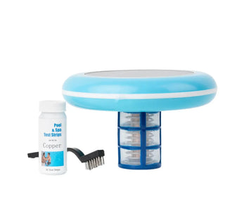
Maintaining your solar pool ionizer's copper anode is not just another pool maintenance task it's a critical procedure that directly impacts your system's sanitization effectiveness, energy efficiency, equipment longevity, and overall pool water quality. Unlike traditional chlorine systems where chemical levels can be easily adjusted, ionization systems rely on precise electrochemical processes that are profoundly affected by anode condition. This comprehensive guide explores every aspect of copper anode maintenance, providing scientifically-backed recommendations, step-by-step procedures, and advanced optimization strategies.
The copper anode in your solar ionizer serves as the primary source of sanitizing ions through controlled electrochemical erosion. As this essential component functions, it naturally accumulates mineral scale, develops surface irregularities, and undergoes physical changes that affect its performance. Understanding the science behind these changes and implementing proper maintenance protocols can extend anode life by 300-400%, reduce your pool's chemical requirements by 40-60%, and prevent common problems like ineffective sanitization, cloudy water, or staining issues.
Table of Contents
- The Electrochemical Science Behind Anode Degradation
- Optimal Cleaning Frequency: Factors That Determine Your Schedule
- Comprehensive Anode Inspection and Assessment Protocol
- Step-by-Step Cleaning Methods: From Basic to Professional
- When to Clean vs. When to Replace: Critical Decision Factors
- Advanced Preventive Strategies to Extend Time Between Cleanings
- Troubleshooting Common Anode Problems and Performance Issues
1. The Electrochemical Science Behind Anode Degradation
Understanding the fundamental electrochemical processes occurring at your copper anode provides the foundation for effective maintenance. Solar pool ionizers operate on the principle of electrolysis, where photovoltaic cells convert sunlight into direct current (typically 12-48 volts at 0.5-3.0 amps) that passes between copper (and often silver) electrodes suspended in your pool's water flow. This electrical circuit creates an electrochemical cell where your pool water serves as the electrolyte, facilitating the controlled release of sanitizing ions while simultaneously initiating processes that degrade the anode over time.
The efficiency of this system depends on maintaining optimal conditions at the electrode interfaces. When scaling, passivation, or uneven erosion occurs, the carefully balanced electrochemical reactions become disrupted, leading to decreased sanitizer production, increased energy consumption, and accelerated equipment degradation. By comprehending these underlying principles, you can implement maintenance strategies that address root causes rather than merely treating symptoms.
The Primary Anode Reaction: Controlled Sanitizer Production
Copper atoms at the anode surface undergo oxidation according to the half-cell reaction: Cu(s) → Cu²⁺(aq) + 2e⁻. This electrochemical process occurs at a standard electrode potential of +0.34 volts relative to the Standard Hydrogen Electrode (SHE). The rate of copper ion release follows Faraday's Law of Electrolysis, where each ampere-hour of current theoretically liberates 1.185 grams of copper into solution, though practical efficiency typically ranges between 70-90% due to competing reactions and system losses.
This controlled erosion releases copper ions into your pool water at a rate proportional to current flow, typically 0.1-0.5 grams per day depending on system size, sun exposure, and water conductivity. These copper ions provide the primary algistatic and bacteriostatic action through multiple mechanisms: they disrupt enzyme systems in microorganisms, interfere with photosynthesis in algae, and damage cellular membranes. The ions remain active in water for extended periods, providing residual sanitization that reduces reliance on traditional chlorine chemicals by 50-90% in well-maintained systems.
Secondary Reactions Leading to Degradation:
- Mineral Scaling Mechanisms: Calcium and magnesium carbonates in clear pool water precipitate onto the anode surface, forming insulating layers that reduce effective surface area. Scale formation follows the inverse solubility principle these minerals become less soluble as water temperature increases and pH rises, both common conditions in solar-exposed pools. The scaling process initiates at nucleation sites on the anode surface, where microscopic imperfections or existing deposits provide low-energy surfaces for crystal growth. The rate of scaling follows an exponential relationship with the Langelier Saturation Index (LSI), with each 0.3 unit increase in LSI typically doubling scaling rate under constant conditions.
- Copper Redeposition Complexities: Some copper ions redeposit as metallic copper or copper oxides in different locations on the anode, creating uneven surface topography that alters current distribution and creates "hot spots" of accelerated erosion. This phenomenon occurs primarily through two mechanisms: electrochemical reduction where copper ions gain electrons at cathodic sites on the anode surface (Cu²⁺ + 2e⁻ → Cu), and cementation where copper replaces less noble metals in the water (Cu²⁺ + Fe → Cu + Fe²⁺). The resulting uneven surface creates localized high-current-density areas that erode 3-5 times faster than smooth surfaces, leading to premature anode failure.
- Passivation Layer Formation Dynamics: Copper oxides (Cu₂O and CuO) naturally form on the anode surface, creating a semiconducting layer that increases electrical resistance. Cuprous oxide (Cu₂O) forms initially as a reddish layer with a bandgap of 2.0 eV, while cupric oxide (CuO) develops as a black layer with a 1.2 eV bandgap. While some passivation is normal and can actually protect the anode from excessive corrosion, excessive buildup (typically >10 μm thickness) significantly reduces ion production efficiency by increasing the voltage required to drive current through the system. The passivation layer growth follows parabolic kinetics, meaning it slows over time but never completely stops.
- Galvanic Corrosion Effects: When copper anodes are paired with dissimilar metals (like stainless steel housings or silver cathodes), galvanic cells can develop, accelerating corrosion in specific areas despite the system being electrically isolated during non-operation periods. The galvanic series determines which metal becomes anodic copper is generally cathodic to zinc and aluminum but anodic to silver and stainless steel in pool water environments. This creates localized corrosion cells where current flows between dissimilar metals through the electrolyte (pool water), with the more anodic metal corroding preferentially. Even small potential differences of 50-100 millivolts can increase corrosion rates by 10-100 times in conductive pool water.
- Hydrogen Evolution Complications: At the cathode (typically silver or stainless steel), water reduction occurs: 2H₂O + 2e⁻ → H₂ + 2OH⁻. The hydroxide ions produced increase local pH dramatically (often reaching pH 9-10 near the cathode surface), which accelerates scaling reactions when this alkaline water circulates back to the anode area. The hydrogen gas produced can create microbubbles that adhere to the anode surface, creating isolated areas where scaling and corrosion patterns differ from the surrounding surface.
- Organic Fouling Interactions: Organic compounds from bather waste, lotions, and environmental debris can adsorb onto the anode surface, creating sites for microbiologically influenced corrosion (MIC). Bacteria colonies can establish on these organic films, creating localized acidic conditions through metabolic byproducts that accelerate copper dissolution in specific patterns. This biological component often creates distinctive pit formations rather than uniform corrosion.
The Scaling-Acceleration Cycle: A Vicious Feedback Loop
The degradation processes interact in a self-reinforcing cycle that explains why poorly maintained anodes often fail catastrophically rather than gradually:
- Initial Scale Formation: Mineral deposits begin forming at nucleation sites on the anode surface, creating initial insulating patches.
- Increased Electrical Resistance: These insulating areas reduce effective surface area, increasing current density on remaining exposed areas.
- Voltage Compensation: The controller or solar panel increases voltage to maintain set current, typically rising from 12-15V to 18-24V in advanced stages.
- Localized Heating: Higher current density and voltage generate increased resistive heating at the anode-electrolyte interface, raising local temperature by 5-15°C above cloudy pool water temperature.
- Accelerated Scaling: Increased temperature reduces mineral solubility (inverse solubility of calcium carbonate = -0.015 g/100mL per °C), dramatically accelerating further scale deposition.
- Hot Spot Development: Uneven scaling creates areas of particularly high resistance and heating, leading to thermal runaway conditions where scaling rates increase exponentially.
- Catastrophic Failure: The cycle continues until either the anode becomes completely insulated (stopping ion production) or thermal stress causes physical failure (cracking or melting).
This positive feedback loop has a time constant typically ranging from 2-8 weeks under poor conditions, meaning that once significant scaling begins, complete anode failure can occur within one to two months without intervention. The cycle is particularly rapid in solar systems because they often operate during peak sunlight hours when water temperatures are highest, creating ideal conditions for both scaling initiation and acceleration.
Electrochemical Efficiency Metrics and Monitoring:
Understanding anode degradation requires monitoring key efficiency metrics:
- Current Efficiency: Ratio of actual copper released to theoretical Faraday prediction. Degradation reduces this from optimal 85-95% down to 30-50% in severely scaled anodes.
- Voltage Efficiency: Percentage of applied voltage actually performing useful work (ion production). Scaling can reduce this from 70-80% to 20-30% as more voltage is wasted overcoming scale resistance.
- Energy Efficiency: Overall kWh per gram of copper produced. Well-maintained systems achieve 0.8-1.2 kWh/g, while scaled systems deteriorate to 3-5 kWh/g.
- Surface Area Utilization: Percentage of geometric surface area actively participating in ion production. Fresh anodes achieve 90-95%, scaled anodes drop to 30-60%.
By tracking these metrics through regular testing and observation, you can detect degradation in its early stages, when intervention is most effective and least costly. The subsequent sections of this guide build upon this electrochemical foundation to provide practical maintenance strategies that interrupt these degradation cycles before they compromise system performance.

2. Optimal Cleaning Frequency: Factors That Determine Your Schedule
There is no universal "clean every X months" recommendation that applies to all solar pool ionizer installations, as attempting to apply a one-size-fits-all schedule often leads to either wasted maintenance effort or catastrophic system failure. The optimal cleaning frequency depends on a complex interplay of water chemistry, environmental conditions, system design, and usage patterns that create unique operational fingerprints for each installation. However, most residential systems fall into one of three maintenance categories, with the majority requiring customized schedules that evolve with seasonal changes and system aging.
Developing your personalized maintenance schedule requires understanding that anode cleaning is not merely about removing visible scale it's about maintaining the delicate electrochemical balance necessary for efficient ion production. Cleaning too frequently wastes time, accelerates anode wear through unnecessary handling and chemical exposure, and disrupts the beneficial passivation layer that develops on properly maintained copper surfaces. Cleaning too infrequently allows scaling to reach critical levels where removal becomes difficult, permanent damage occurs, and system efficiency plummets, often requiring 3-5 times more energy to produce the same sanitizer levels.
Standard Maintenance Schedule Guidelines:
- Basic Recommendation (Starting Point for Most Systems): Every 3-4 months during peak swimming season (May-September in temperate climates). This assumes moderate water hardness (200-300 ppm calcium), average sun exposure, and residential usage patterns. This schedule maintains system efficiency between 75-90% of optimal.
- High-Maintenance Conditions (Multiple Risk Factors Present): Every 4-6 weeks when one or more risk factors are present. These include: pool hard water (>400 ppm calcium), full sun exposure in hot climates, high bather loads (>10 person-hours daily), poor water balance management, or systems with design limitations (low flow rates, small anode surface area). This aggressive schedule prevents efficiency from dropping below 60%.
- Low-Maintenance Conditions (Optimized Systems): Every 6-8 months with optimized water chemistry and favorable conditions. Achievable with: softened fill water (<150 ppm calcium), consistent pH control (7.2-7.4), proper alkalinity management (60-80 ppm), partial shading during peak sun, and moderate usage. These systems typically maintain 85-95% efficiency between cleanings.
- Winter/Off-Season Protocol: Clean before winterizing and after reopening (2x yearly in seasonal climates). The pre-winter cleaning removes scale that could harden and become difficult to remove after months of dormancy. The post-winter cleaning addresses any corrosion or minor scaling that occurred during storage. In year-round warm climates, maintain your regular schedule but reduce frequency by 20-30% during cooler months when scaling rates decrease naturally.
Primary Factors Influencing Cleaning Frequency:
Water Chemistry Parameters (The Foundation):
- Calcium Hardness: The single most important factor in scaling rate determination. Below 200 ppm: minimal scaling (6-8 month intervals). The scaling rate follows approximately cubic relationship with calcium concentration doubling calcium increases scaling rate 8-fold. At 200-400 ppm: moderate scaling (3-4 month intervals). Above 400 ppm: aggressive scaling (4-8 week intervals) with rapid efficiency loss. The critical threshold is 250 ppm above this, each 50 ppm increase reduces time between cleanings by approximately 25%.
- Total Alkalinity: High alkalinity (>120 ppm) accelerates carbonate scaling, particularly when combined with high pH. Maintain 60-80 ppm for ionizer systems this provides sufficient buffering while minimizing scaling potential. Each 20 ppm increase in alkalinity above 80 ppm typically reduces cleaning interval by 15-20%. The alkalinity-to-calcium ratio is also critical: aim for 0.3-0.5 (alkalinity/calcium) for optimal balance.
- pH Levels: Every 0.3 pH unit increase above 7.4 approximately doubles scaling potential due to increased carbonate ion concentration. Maintain 7.2-7.4 for optimal performance this narrow range represents the sweet spot between copper solubility and scaling prevention. pH control is particularly critical in solar systems as sunlight increases photosynthesis in any algae present, raising pH through CO₂ consumption.
- Total Dissolved Solids (TDS): Above 1500 ppm increases all precipitation reactions through the common ion effect and reduced solubility. Each 500 ppm increase in TDS typically reduces cleaning interval by 20-30%. Implement partial water replacement when TDS exceeds 2000 ppm or increases by 1000 ppm above fill water baseline. Monitor TDS monthly with a calibrated conductivity meter.
- Silica Content: Often overlooked, silica in fill water (>30 ppm) forms glass-like silicate scales that are extremely difficult to remove. These create permanent insulating layers that require professional treatment. Test fill water for silica annually or when moving to aggressive cleaning schedules despite good calcium control.
Environmental and Usage Factors (The Modifiers):
- Sun Exposure and Temperature Dynamics: Systems in full sun with water temperatures consistently above 85°F require 30-50% more frequent cleaning. Each 10°C (18°F) temperature increase doubles chemical reaction rates through Arrhenius equation kinetics. More critically, solar gain on the ionizer housing itself can create localized hot spots 10-15°C above pool temperature, dramatically accelerating scaling at the exact location where it's most damaging. Shading the ionizer unit during peak sun hours (11am-3pm) can extend cleaning intervals by 40-60%.
- Bather Load Impact Analysis: High usage introduces organic compounds, oils, and suspended solids that deposit on anodes, creating nucleation sites for scale formation. Commercial pools or large family pools (>10 swimmers daily) may need monthly cleaning during peak season. Each additional 5 person-hours per day typically reduces cleaning interval by 10-15%. Organic films also promote microbiologically influenced corrosion (MIC), creating localized pitting that requires more frequent inspection.
- Fill Water Quality Assessment: Hard well water or municipal water with high mineral content accelerates scaling. Test your fill water's calcium, magnesium, and silica content seasonally municipal water supplies often change sources or treatment methods. Consider installing a water softener specifically for pool top-up if fill water exceeds 300 ppm calcium. The cost-benefit analysis typically favors softening when cleaning frequency exceeds every 8 weeks due to water hardness alone.
- Geographic Location Considerations: Desert climates with high evaporation (60+ inches annually) concentrate minerals 3-5 times faster than humid climates. Implement continuous overflow systems or more frequent partial drains. Humid climates with frequent rainfall dilute minerals but may increase organic loading from environmental debris. Coastal regions face salt spray contamination that increases chloride levels, accelerating corrosion rather than scaling.
- Seasonal Weather Patterns: Spring pollen, summer dust storms, autumn leaf debris, and winter atmospheric inversions all introduce particulates that accelerate scaling. Adjust cleaning schedule based on local environmental conditions typically 25% more frequent during high-particulate seasons.
System-Specific Factors (The Hardware Variables):
- Current Density Effects: Higher current systems (typically commercial units >2 amps) erode anodes faster and generate more heat through I²R heating, accelerating scaling. Current density above 20 mA/cm² creates significant localized heating. For adjustable systems, operate at the lower end of the recommended range reducing current by 30% typically extends cleaning intervals by 40-50% with minimal impact on sanitizer production due to improved efficiency.
- Anode Composition and Microstructure: Pure copper (C110) versus copper alloys with tellurium or phosphorus have different scaling characteristics. Tellurium-copper alloys (C145) resist scaling better but cost 2-3 times more. The surface finish matters smooth machined surfaces scale slower than rough cast surfaces. Electropolished anodes can extend intervals by 25-35% compared to standard finishes.
- Flow Rate and Hydraulic Design: Systems with turbulent flow across the anode (Reynolds number >4000) provide mechanical scrubbing action that can extend cleaning intervals by 20-30%. Laminar flow designs accumulate deposits more quickly in stagnant boundary layers. Optimal flow velocity is 1-2 feet per second below 0.5 fps dramatically increases scaling; above 3 fps causes excessive erosion.
- System Age and Surface Evolution: New anodes (first 6 months) often require more frequent cleaning as the surface develops its working microstructure and passivation layer. This break-in period typically needs 50% more frequent attention. Older systems (>3 years) may have established scaling patterns or surface roughening that either increases or decreases scaling rates depending on whether scale adheres more or less easily to the modified surface.
- Controller Sophistication: Advanced systems with pulse-width modulation, reverse polarity cleaning cycles, or adaptive current control can extend cleaning intervals by 30-70% compared to basic on/off systems. These features actively combat scale formation during normal operation rather than relying solely on periodic manual cleaning.
Diagnostic Signs for Schedule Adjustment:
Signs You're Cleaning Too Infrequently (Immediate Action Required):
- Visible scale thickness exceeds 1/16 inch (1.5 mm) measure with calipers at multiple points
- Ion production decreases measurably (copper test strips show <0.2 ppm despite normal operation)
- Visible pool algae growth in pool despite system operation indicates insufficient sanitizer production
- System runs noticeably warmer to touch (ΔT >5°C above ambient water temperature)
- Voltage reading increases by more than 15% from clean baseline at same current setting
- Current draw decreases by more than 20% at same voltage setting (indicates increased resistance)
- Cleaning requires aggressive acid soaking (>10 minutes in 10% HCl) or mechanical scraping
- Scale removal reveals pitted or corroded surface underneath (damage has already occurred)
- System produces audible crackling or popping sounds during operation (scale breaking under thermal stress)
Signs You're Cleaning Too Frequently (Wasting Resources):
- Anode shows accelerated wear patterns after just 2-3 cleanings (measurable diameter reduction >5% per year)
- Surface becomes pitted or develops deep grooves from over-aggressive cleaning methods
- Copper consumption increases noticeably (anode replacement needed more often than every 2 years)
- No significant scale buildup visible between cleanings (<0.5 mm thickness after 3+ months)
- System efficiency doesn't improve measurably after cleaning (voltage/current readings unchanged)
- Anode develops shiny, bright copper appearance after cleaning (indicating removal of beneficial passivation layer)
- Maintenance records show similar conditions at each cleaning (no progression of scaling severity)
- Water chemistry parameters remain stable between cleanings (no increasing scaling risk factors)
The Progressive Adjustment Method:
Instead of guessing your optimal schedule, use this systematic approach:
- Start Conservative: Begin with the 3-4 month schedule for your first season
- Document Everything: Record scale thickness, cleaning difficulty, and performance metrics each time
- Analyze Trends: After 2-3 cleanings, identify whether conditions are improving, worsening, or stable
- Make Small Adjustments: Change interval by 2-4 weeks based on findings, not more than 25% at once
- Consider Seasonal Variations: Create separate schedules for peak summer, shoulder seasons, and winter
- Re-evaluate Annually: Water chemistry, usage patterns, and pool equipment condition change over time
Remember that the goal isn't to eliminate cleaning entirely, but to find the sweet spot where maintenance effort, system efficiency, and anode longevity are optimally balanced. Most well-tuned systems settle into a rhythm where cleaning becomes a predictable, brief procedure rather than an emergency response to system failure.

3. Comprehensive Anode Inspection and Assessment Protocol
Proper inspection transforms anode maintenance from guesswork to predictive science. Implementing a systematic assessment protocol each time you access your ionizer enables data-driven decision making, early problem detection, and optimization of your entire maintenance strategy. This comprehensive 15-point assessment protocol goes beyond superficial visual checks to provide quantitative metrics that reveal underlying system health, predict future failures, and validate the effectiveness of your maintenance practices over time.
The inspection process should be approached with the precision of an industrial maintenance engineer rather than the casual observation of a typical pool owner. Each inspection point yields specific data that, when combined and analyzed over multiple cycles, reveals patterns and trends invisible during any single examination. This systematic approach allows you to catch minor issues before they become major problems, optimize cleaning schedules based on actual wear patterns rather than calendar dates, and extend anode lifespan through proactive intervention.
Detailed Visual Inspection Checklist (The Foundation):
1. Scale Color, Texture, and Composition Analysis:
- White/Chalky Deposits: Primarily calcium carbonate (CaCO₃). Soft, easily removed with mild acid. Indicates hard water with adequate pH control. Thickness progression rate helps calculate water hardness impact.
- Gray/Brown Accumulations: Mixed minerals with organic matter, often including calcium phosphate, magnesium silicate, and adsorbed organics. Requires combined acid and mechanical removal. Suggests high bather load or environmental debris.
- Green/Blue Coloration: Copper compounds basic copper carbonate (malachite, Cu₂CO₃(OH)₂) or copper hydroxide (Cu(OH)₂). Hard, crystalline deposits requiring stronger acids. Indicates localized high pH conditions or copper redeposition.
- Black/Brown Hard Crust: Manganese oxides or iron compounds from fill water. Extremely difficult to remove, often requiring specialized cleaners. Test fill water for transition metals.
- Yellowish/Tan Films: Silica-based scales or sulfur compounds. Glass-like hardness, often permanent damage. Indicates high silica fill water or bacterial sulfate reduction.
Texture Assessment: Use pick test gently probe scale with plastic tool. Hard, crystalline = carbonate dominant. Soft, powdery = recently formed or organic-rich. Laminated layers = alternating pool water chemistry conditions.
2. Scale Distribution Pattern Analysis:
- Uniform Coating: Even current distribution and consistent flow patterns. Ideal condition indicating well-designed system and good water circulation.
- Patchy or Streaked Patterns: Suggests flow issues, uneven electrical contact, or variable current density. Look for correlation with flow direction or proximity to connection points.
- Heavy Scaling on Upstream Side: Clear flow-direction effects. May indicate insufficient flow velocity or boundary layer separation. Consider flow straighteners or increased pump runtime.
- Concentric Ring Patterns: Seasonal or cyclical water chemistry variations. Each ring represents a period with different scaling conditions. Document to identify seasonal patterns.
- Localized Heavy Scaling: Hot spots indicating current concentration or localized heating. Measure temperature differential with infrared thermometer if possible.
- Shadowing Effects: Areas behind mounting brackets or other obstructions show different scaling patterns, revealing flow characteristics and potential dead zones.
3. Quantitative Scale Thickness Measurement Protocol:
- Use digital calipers with 0.01mm resolution at minimum 8 standardized points: four quadrants at both ends and middle of anode.
- Measure both scale thickness and total diameter (scale + anode) at each point.
- Calculate: Maximum thickness, minimum thickness, average thickness, standard deviation (indicates uniformity).
- Progressive thickening indicates: Inadequate cleaning frequency, worsening water conditions, or reduced cleaning effectiveness.
- Critical thresholds: >1.0mm = immediate cleaning needed; >2.0mm = potential permanent damage; >3.0mm = emergency situation.
- Calculate scaling rate: (Current thickness - Previous thickness) / Days since last cleaning = mm/day scaling rate.
4. Surface Erosion Pattern Analysis:
- Smooth, Even Erosion: Ideal condition indicating uniform current distribution and proper flow characteristics.
- Concentrated Erosion at Edges: Current concentration at sharp geometric features. Consider radiused edges on replacement anodes.
- Grooves or Channels: Flow-induced erosion or manufacturing defects. Deep grooves (>0.5mm) create stress concentration points.
- Pitting Corrosion: Localized deep pits rather than general erosion. Indicates: Chloride attack, microbiological influence, or metallurgical defects.
- Uneven Diameter Reduction: Measure diameter at 1-inch intervals along length. More than 10% variation indicates serious current distribution problems.
- Step-like Erosion Patterns: Sudden changes in erosion rate, often corresponding to scale layer boundaries or seasonal operation changes.
5. Discoloration and Corrosion Analysis:
- Dark Gray/Black Areas: Copper oxide passivation layers (Cu₂O, CuO). Normal in small amounts; excessive indicates low current operation or extended off-periods.
- Pinkish/Reddish Areas: Copper depletion revealing underlying alloy components or dezincification in brass alloys. Critical finding requiring immediate investigation.
- Green Patina: Basic copper compounds indicating prolonged wetness during off-cycles or inadequate drying after cleaning.
- Rainbow Coloration: Thin film interference indicating very smooth surface or special coatings.
- Selective Leaching Patterns: Preferential removal of specific alloy components, often appearing as mottled or spotted surfaces.
6. Connection Point Integrity Assessment:
- Check for corrosion at wire connections using magnification if possible.
- Test connection resistance: Should be <0.1 ohms between anode body and wire end.
- Look for signs of overheating: Discolored insulation, melted solder, oxidation rings.
- Check tightness: Connections should be snug but not over-tightened (typically 10-15 in-lbs).
- Inspect for galvanic corrosion: Different metal connections create bimetallic corrosion cells.
- Evaluate wire condition: Flexibility, insulation integrity, strand breakage.
7. Structural Integrity Evaluation:
- Visual inspection for cracks using bright light and magnification.
- Bend test: Gentle pressure should reveal any hidden cracks or weaknesses.
- Measure diameter at multiple points: More than 10% reduction from original indicates replacement time.
- Check straightness: Place on flat surface, should not rock or show gaps >0.5mm.
- Tap test: Metallic ring indicates solid structure; dull thud suggests internal defects.
- Weight comparison: More than 20% weight loss from original indicates advanced depletion.
Performance-Based Assessment (Quantitative Metrics):
8. Electrical Parameter Documentation Protocol:
- Pre-Cleaning Measurements: Document operating voltage and current with system at normal operation. Use calibrated multimeter with 1% accuracy minimum.
- Resistance Calculation: R = V/I. Compare to clean baseline. Increase >15% indicates significant scaling.
- Power Consumption: P = V × I. Increased power with same output indicates efficiency loss.
- Start-up Transients: Observe voltage/current during first 5 minutes of operation. Unstable readings indicate connection problems or severe scaling.
- Compare to Manufacturer Specifications: Document percentage deviation from original performance specs.
- Temperature Correlation: Measure housing temperature with IR thermometer. >10°C above water temperature indicates excessive resistance heating.
9. Ion Production Rate Calculation:
- Weight Method: Weigh anode before installation and at each inspection using precision scale (0.1g accuracy).
- Calculate Daily Erosion Rate: Weight loss (g) / Days operated = g/day.
- Expected Ranges: Residential: 0.1-0.3g/day; Commercial: 0.3-0.8g/day.
- Significantly Less: Scaling interference or insufficient current.
- Significantly More: Electrical issues, incorrect installation, or water chemistry problems causing excessive erosion.
- Efficiency Calculation: Actual erosion / Theoretical (Faraday) erosion × 100%. Target: 70-90%.
10. Water Test Correlation Analysis:
- Copper Ion Concentration: Test pool water at same time as inspection. Use reliable test method (photometer preferred).
- Target Range: 0.3-0.5 ppm for most residential systems.
- Consistently Low: Scaling problems, anode depletion, or insufficient runtime.
- Erratically High: Overproduction, poor circulation, or testing error.
- Correlation with Erosion Rate: Expected: 0.1g copper/day ≈ 0.1 ppm in 20,000 gallon pool with daily turnover.
- Distribution Testing: Test multiple pool locations. Significant variations indicate circulation problems affecting ion distribution.
11. Solar Performance Assessment (Unique to Solar Systems):
- Measure solar panel output voltage/current at time of inspection.
- Compare to manufacturer specs and clean baseline.
- Check for shading, dirt accumulation, or panel degradation.
- Document sun conditions: Clear, partly cloudy, overcast.
- Calculate solar-to-ion efficiency: (Ion production rate) / (Solar energy input).
Advanced Diagnostic Procedures (Optional but Valuable):
12. Microscopic Examination (If Available):
- Use 10-30× magnification to examine surface details.
- Look for: Crack initiation points, intergranular corrosion, pit morphology.
- Document with photos through microscope or macro lens.
13. Dye Penetrant Testing (For Suspected Cracks):
- Apply fluorescent dye penetrant to cleaned, dry anode.
- Allow dwell time, then clean and apply developer.
- Inspect under UV light for crack indications.
14. Electrochemical Testing (Professional Level):
- Measure open circuit potential relative to reference electrode.
- Perform simple polarization resistance measurement to calculate corrosion rate.
- Compare to established values for copper in pool water.
Documentation and Trend Analysis System:
15. Comprehensive Maintenance Log Requirements:
Maintain a detailed digital or physical log with these minimum data points:
- Basic Information: Inspection date, time, inspector name, weather conditions
- Visual Documentation: Photographs from multiple angles with scale reference, close-ups of problem areas
- Quantitative Measurements: Scale thickness at all measured points, diameter measurements, weight
- Electrical Parameters: Voltage, current, resistance, power consumption (pre- and post-cleaning)
- Water Chemistry: pH, alkalinity, calcium hardness, TDS, copper level, temperature at time of inspection
- Performance Data: Calculated erosion rate, efficiency percentage, solar panel output
- Maintenance Actions: Cleaning method used, chemicals and concentrations, duration, results
- Observational Notes: Any unusual findings, patterns noticed, changes from previous inspection
- System Operation Data: Daily runtime hours for period since last inspection, bather load estimate, any system modifications
Trend Analysis and Predictive Maintenance:
- Graph scale thickness over time slope indicates scaling rate acceleration or deceleration
- Plot electrical resistance versus time increasing slope indicates deteriorating condition
- Correlate water chemistry parameters with scaling rates to identify primary drivers
- Calculate remaining anode life: (Current diameter : Minimum acceptable diameter) / Erosion rate
- Identify seasonal patterns to optimize cleaning schedule timing
- Use statistical process control methods to identify when parameters move outside normal variation
This comprehensive inspection protocol, when implemented consistently, transforms anode maintenance from reactive repair to predictive science. The data collected enables optimization of every aspect of system operation, from cleaning schedules to water chemistry management to equipment replacement planning. Most importantly, it provides early warning of developing problems, allowing intervention when corrections are simple and inexpensive rather than waiting for catastrophic failure requiring complete system replacement.

4. Step-by-Step Cleaning Methods: From Basic to Professional
Selecting the appropriate cleaning method is a critical decision that balances effectiveness against potential damage to your valuable anode. The optimal approach depends on three key factors: scale composition (determined during your inspection), current anode condition (including any existing damage or wear patterns), and the tools and chemicals safely available to you. Always adhere to the fundamental principle of progressive intervention: begin with the gentlest effective method and progress to more aggressive techniques only when milder approaches prove insufficient. This conservative strategy preserves anode material, maintains surface integrity, and extends overall system lifespan.
Each cleaning method carries inherent trade-offs between cleaning power and potential side effects. Mild methods preserve anode integrity but may require more frequent application. Aggressive methods solve immediate problems but can accelerate long-term degradation if used indiscriminately. The most skilled maintainers develop the ability to match method to situation based on systematic assessment rather than defaulting to familiar approaches. This section provides detailed protocols for four distinct cleaning methodologies, ranging from routine maintenance to emergency restoration.
Method 1: Mild Acid Soak (For Light, Recent Scale)
Ideal Applications: White, chalky calcium carbonate scale less than 1/32 inch (0.8 mm) thick, formed within the last 4-8 weeks. Also effective for soft, powdery deposits that haven't yet bonded strongly to the copper surface. Suitable for routine maintenance in well-balanced pools with moderate water hardness.
Solution Preparation: 10% citric acid or white vinegar solution (1 part acid to 9 parts water). Citric acid is preferred as it's less odoriferous and provides more consistent results. For vinegar, use distilled white vinegar (5% acidity) rather than apple cider or wine vinegars which contain additional compounds. Prepare in clean polyethylene or polypropylene container with at least 50% extra volume to accommodate foaming.
Detailed Procedure:
- Remove anode from ionizer housing following manufacturer instructions, noting orientation and connection configuration for reassembly.
- Pre-rinse anode with clear pool water to remove loose debris and organic matter that could interfere with acid action.
- Submerge anode completely in acid solution using non-metallic holder (plastic clip or string). Ensure all scaled surfaces contact the solution.
- Observe reaction: Bubbling (carbon dioxide release) should begin within 30-60 seconds. If no bubbling occurs within 2 minutes, scale may not be acid-soluble or may require stronger treatment.
- Soak for 5-15 minutes, gently agitating container every 2-3 minutes to refresh solution contact. Continue until bubbling substantially decreases or stops completely.
- Remove anode and immediately rinse under running water for 60 seconds to halt acid action.
- Light brushing with soft nylon brush if any residue remains, using gentle circular motions rather than abrasive scrubbing.
- Final rinse with distilled or deionized water if available to prevent water spot deposits.
- Dry completely using lint-free cloth followed by air drying for at least 30 minutes. Ensure connection points and threads are completely moisture-free.
- Visually inspect under good lighting to verify complete scale removal before reinstalling.
Safety Protocol: Wear nitrile gloves (not latex) and splash-proof goggles. Work in well-ventilated outdoor area away from children and pets. Never mix different acids. Have baking soda solution (1 cup per gallon water) readily available for accidental spills or splashes. Dispose of used acid solution by diluting with ample water and pouring down drain with continued water flow.
Effectiveness Limitations: This method removes only carbonate-based scales. It will not affect silicate deposits, metallic oxides, or heavily bonded mixed scales. If scale remains after 15-minute treatment, progress to Method 2 rather than extending soak time, as prolonged mild acid exposure can still damage copper over extended periods.
Method 2: Moderate Acid Cleaning (For Moderate Scale)
Ideal Applications: Mixed mineral scale 1/32 to 1/16 inch (0.8-1.6 mm) thick, scale resistant to mild acids, or situations where time between cleanings has exceeded optimal intervals. Effective for calcium carbonate with embedded organic matter or beginning stages of copper compound formation.
Solution Preparation: 10% muriatic (hydrochloric) acid solution. CRITICAL: ALWAYS add acid to water slowly while stirring, never water to acid. Use 1 part 31.45% muriatic acid to 2 parts water (this yields approximately 10% final concentration). Prepare in heavy-duty polyethylene container specifically rated for acid storage, with minimum 100% extra volume to contain vigorous foaming. Pre-chill water if possible to reduce reaction heat.
Detailed Procedure:
- Complete all preparation and safety measures before exposing anode to acid. Assemble all equipment within reach.
- Submerge anode completely using non-metallic holder, ensuring no air pockets trap scale from solution contact.
- Monitor closely with timer: Typical reaction time 2-8 minutes depending on scale thickness and temperature. Vigorous bubbling indicates active scale removal.
- Check progress at 2-minute intervals by briefly lifting anode (with gloves) to inspect. Look for scale softening and color change.
- Remove IMMEDIATELY when bubbling substantially decreases (not necessarily stops completely) to prevent copper etching. Maximum soak time: 10 minutes regardless of bubbling status.
- Immediately transfer to neutralizing bath: baking soda solution (1 cup sodium bicarbonate per gallon water) for 2 minutes with gentle agitation.
- Rinse thoroughly with running water for at least 2 minutes, ensuring all acid residues are flushed from crevices and connection points.
- Inspect for "pink blush" appearance indicating copper surface exposure. This is normal but indicates passivation layer has been removed.
- Dry completely using compressed air if available, followed by warm air (not exceeding 50°C/122°F). Moisture in reassembled unit creates galvanic corrosion cells.
- Weigh anode after drying if tracking erosion rates acid cleaning removes negligible copper when properly controlled.
Critical Warnings: Muriatic acid will etch and pit copper if left too long or at excessive concentration. Never exceed 10% concentration or 10 minute soak time. Acid temperature should not exceed 40°C (104°F) during reaction if solution becomes hot, remove anode immediately and allow cooling. Work upwind of acid container to avoid vapor inhalation. Double-bag disposal of used solution with absorbent material.
Scale-Specific Adjustments: For scale with visible green/blue copper compounds, reduce concentration to 5% and maximum time to 5 minutes. For organic-rich brown scale, pre-soak in enzymatic cleaner for 30 minutes before acid treatment to break down organic matrix.
Method 3: Electrolytic Cleaning (Professional Technique)
Ideal Applications: Heavy, stubborn scale (>1/16 inch), complex mixed deposits, situations where acid contact is undesirable, or when mechanical cleaning might damage already-thinned anode material. Particularly effective for oxide layers and deeply passivated surfaces that resist chemical cleaning.
Equipment Requirements: 12V battery charger (manual, not automatic), stainless steel cathode (316 grade preferred), 5-10 gallon plastic container, electrolyte solution ingredients, multimeter for current monitoring, non-metallic holders for both electrodes.
Solution Preparation: Electrolyte: 1 tablespoon washing soda (sodium carbonate) per gallon of distilled or deionized water. Avoid tap water with high mineral content. Mix thoroughly until completely dissolved. Solution should be prepared fresh for each use.
Detailed Procedure:
- Set up in well-ventilated area with electrical safety measures: GFCI outlet, dry surfaces, no water near electrical connections.
- Fill container with electrolyte, ensuring sufficient depth to completely subscale scaled areas of anode.
- Suspend anode from negative (black) charger lead using copper wire or alligator clip. Ensure good electrical contact.
- Suspend stainless steel cathode (large surface area preferred) from positive (red) lead, positioning parallel to anode with 2-4 inch separation.
- Verify no direct contact between electrodes at any point during process.
- Apply power starting at 2 amps, monitoring current draw. Adjust to maintain gentle bubbling (approximately 4-6 amps for typical residential anodes).
- Observe process: Hydrogen bubbles form at cathode, scale loosens and falls from anode. Process typically takes 15-45 minutes depending on scale thickness.
- Periodically gently brush anode with plastic brush to dislodge loosened scale (power OFF during brushing).
- For final 2 minutes, reverse polarity (anode becomes positive) to remove any redeposited metallic particles.
- Power off, remove anode, rinse thoroughly with running water, and dry completely.
Key Advantages: Removes scale without acid contact, eliminating etching risk. Uniform cleaning action preserves anode geometry. Can restore deeply passivated anodes to active condition. Environmentally friendlier waste stream (neutral electrolyte versus acid).
Safety Considerations: Hydrogen gas production requires ventilation no open flames or sparks nearby. Electrolyte can become hot during extended operation monitor temperature. Always disconnect power before handling electrodes. Use only manual battery chargers automatic chargers may misinterpret electrolysis as battery condition.
Method 4: Mechanical Cleaning (Last Resort Option)
Ideal Applications: Extreme situations where acids are unavailable, inappropriate due to facility restrictions, or when dealing with non-acid-soluble deposits (silica, some metallic oxides). Also useful for spot treatment of localized heavy scaling after bulk removal by other methods.
Tool Selection Hierarchy:
- Primary: Plastic or wood scraping tools (credit card edges, plastic putty knives, tongue depressors)
- Secondary: Nylon scrubbing pads (white, not colored which may contain abrasives)
- Tertiary: Brass brush (only for stubborn spots after plastic/nylon proves insufficient)
- Finishing: Fine nylon pad (600+ grit equivalent) for surface smoothing
- Specialized: Dental picks (plastic) for crevice cleaning
Detailed Procedure:
- Soak anode in warm water for 30-60 minutes to soften scale if possible. Adding a surfactant (drop of dish soap) can improve water penetration.
- Use plastic scraper at shallow angle (10-20°) to remove bulk scale gently. Work in direction parallel to anode length, not circumferential.
- Follow with nylon scrubbing pad using circular motions with moderate pressure. Change pads frequently as they load with debris.
- For stubborn spots, use brass brush with light pressure and minimal strokes. Brass is softer than copper but harder than scale.
- Rinse frequently under running water to remove debris and inspect progress. Use magnifying glass if available to check for remaining scale.
- Final polish with fine nylon pad using longitudinal strokes to create uniform surface finish.
- Ultrasonic cleaner optional: If available, 10-minute ultrasonic bath in water with mild detergent can remove final particles.
Critical Prohibitions: NEVER use steel tools, brushes, or wool they contaminate anode with iron particles that create galvanic corrosion sites. Avoid aggressive scraping that creates deep grooves or alters anode geometry. Do not use power tools (Dremel, etc.) as they remove excessive material and create uneven surfaces.
Damage Assessment: After mechanical cleaning, inspect carefully for: scratches deeper than 0.005 inch, grooves, altered dimensions, or surface discoloration indicating excessive material removal. Measure diameter at cleaned areas versus original specifications.
Post-Cleaning Treatment and Protection Protocol:
Passivation Restoration:
After acid cleaning, anodes lose their protective oxide layer, leaving chemically active surfaces prone to rapid re-scaling and uneven initial erosion. Some professionals recommend a brief soak in mild hydrogen peroxide solution (3%, 1-2 minutes) to restore a thin, uniform oxide coating. Alternative method: expose to air for 24 hours before reinstalling to allow natural oxidation. For critical applications, some use proprietary passivation solutions designed specifically for copper electrodes.
Surface Conditioning:
Light polishing with fine (0000) steel wool can create more uniform surface for even current distribution, but removes minimal material (typically <0.001 inch). Follow with alcohol wipe to remove polishing residues. For anodes showing erosion patterns, selective polishing of high spots can help redistribute current more evenly.
Connection Maintenance:
- Clean electrical contacts with electronic contact cleaner or fine sandpaper (600 grit).
- Inspect for pitting or corrosion at connection points file smooth if minor, replace components if severe.
- Apply dielectric grease to threads before reassembly to prevent galvanic corrosion while maintaining electrical contact through mating surfaces.
- Torque connections to manufacturer specifications (typically 8-12 in-lbs for residential systems).
System Flush and Commissioning:
- After reinstalling cleaned anode, run pump for 30 minutes without solar power to flush any debris from system.
- Inspect filter pressure increase significant rise indicates scale particles in system requiring backwash or filter cleaning.
- Gradually reintroduce solar power over 15-minute period while monitoring voltage/current.
- Document post-cleaning electrical parameters as new baseline for future comparisons.
- Test copper levels in pool 24 hours after commissioning to verify system functionality.
Method Selection Decision Matrix:
Use this quick-reference guide to choose appropriate method:
- Scale ≤0.8mm, white/chalky: Method 1 (95% success rate)
- Scale 0.8-1.6mm, mixed composition: Method 2 (85% success rate)
- Scale >1.6mm, any composition: Method 3 (75% success rate) or professional service
- Non-acid-soluble deposits: Method 4 followed by Method 3
- Anode <50% original diameter: Method 1 only (preserve material)
- Visible pitting or cracks: Gentle Method 1, consider replacement if cleaning needed
By mastering these cleaning methods and applying them judiciously based on systematic assessment, you can maintain optimal anode performance while maximizing service life. The most effective maintainers develop proficiency with multiple methods, allowing them to address varying conditions with precision rather than relying on a single approach for all situations.

5. When to Clean vs. When to Replace: Critical Decision Factors
Determining whether to clean or replace your copper anode is one of the most consequential decisions in solar ionizer maintenance. This choice represents a fundamental balance between conservation of resources and protection of your entire pool system. Replacement involves significant direct costs and installation effort, but continuing with a depleted or compromised anode carries hidden expenses that often exceed replacement costs: compromised pool sanitation leading to potential health risks, accelerated damage to other system components, increased chemical usage, and the eventual certainty of emergency replacement under unfavorable conditions.
The decision framework requires moving beyond simple visual assessment to incorporate quantitative measurements, performance data, and forward-looking projections. An anode that appears serviceable today may be approaching failure thresholds that will manifest at the most inconvenient time typically mid-summer when pools see heaviest use. Developing a systematic evaluation protocol transforms this critical decision from guesswork to data-driven strategy, ensuring you replace components at the optimal point where maximum value has been extracted without risking system failure.
Absolute Replacement Indicators (Replace Immediately - No Further Use Possible)
These conditions represent immediate safety and operational concerns that preclude any further cleaning or temporary measures. When any of these indicators are present, discontinue use immediately and proceed with replacement:
- Structural Failure: Visible cracks, complete breaks, or severe bending that prevents proper installation or maintains reliable electrical contact. Even hairline cracks can propagate rapidly under operational stress, leading to complete failure during use.
- Extreme Material Loss: Diameter reduced by more than 25% from original specifications, or any section measuring less than 50% of original diameter. These thresholds indicate advanced depletion where remaining material cannot safely carry operational currents without overheating or accelerated failure.
- Connection Point Failure: Stripped threads, broken connection lugs, or severe corrosion at electrical contacts that cannot be cleaned to restore reliable connection. Compromised connections create resistance heating points that can damage controllers and create fire hazards.
- Perforation or Critical Pitting: Actual holes through the anode material or pits deeper than 1/8 inch (3mm) that create stress concentration points. These defects fundamentally compromise structural integrity and create localized high-current-density areas that accelerate further degradation.
- Galvanic Isolation Failure: Evidence of copper deposition on non-copper components indicating the anode is no longer properly isolated electrically, creating uncontrolled galvanic cells that damage other pool equipment.
- Thermal Damage Evidence: Discoloration patterns indicating overheating, melted areas, or recrystallization of copper structure suggesting the anode has experienced temperatures exceeding safe operational limits.
Relative Replacement Indicators (Consider Replacement in Near Future)
These conditions suggest the anode is approaching end of service life and replacement should be planned proactively rather than reactively. While immediate replacement may not be absolutely necessary, delaying beyond the next maintenance cycle often proves counterproductive:
- Accelerated Consumption Rate: Anode losing more than 0.5g/day in residential systems indicates either electrical problems (excessive current) or poor water chemistry causing unnaturally rapid erosion. This unsustainable rate suggests the anode will reach critical depletion much sooner than normal service life expectations.
- Pronounced Uneven Wear Pattern: One side eroded significantly more than another (greater than 30% diameter difference), suggesting current distribution problems that cleaning cannot fix. This indicates fundamental issues with installation geometry, flow patterns, or electrical connections that will continue to affect any anode in the current configuration.
- Increasing Maintenance Frequency: Needing cleaning more than monthly despite optimized water chemistry suggests anode surface degradation has reached a point where scale adheres more readily or forms more rapidly. This often indicates surface roughening, micro-pitting, or chemical changes in the copper that accelerate scaling.
- Age-Based Considerations: Most copper anodes provide reliable service for 2-5 years under normal conditions. Beyond this range, consider replacement even if visual inspection appears acceptable, as material fatigue, cumulative stress, and microscopic degradation may not be visible but can lead to sudden failure.
- Progressive Efficiency Decline: Documented reduction in ion production efficiency (copper ions released per amp-hour) over multiple cleaning cycles, indicating the anode material itself is changing in ways that reduce its electrochemical effectiveness.
- Increased Electrical Resistance: Progressive rise in operating voltage required to maintain target current, not fully resolved by cleaning, suggesting permanent changes in the anode's electrical properties or interfacial characteristics.
The 50% Rule: A Practical Guideline for Residential Systems
A widely accepted practical guideline for residential solar ionizer systems: when your anode has eroded to approximately 50% of its original mass or cross-sectional area, begin serious planning for replacement. This conservative threshold ensures replacement occurs while the anode still has sufficient material to complete a full season if necessary, avoiding mid-season failures during peak swimming periods.
You can estimate remaining life using these methods:
- Diameter Measurement Method: Measure at multiple points along the anode's length using calipers. Compare to original specifications. A 30% diameter reduction corresponds to approximately 50% cross-sectional area loss (since area = πr²).
- Weight Comparison Approach: Weigh the anode using a precision scale and compare to expected new anode weight. Account for any scale that may add weight—clean thoroughly before weighing for accurate assessment.
- Visual Reference Comparison: If you have access to a new anode of the same model, direct visual comparison can be surprisingly revealing. Place them side-by-side under good lighting.
- Volume Displacement Method: For irregular shapes, measure water displacement to estimate remaining volume compared to original specifications.
Remember that the 50% rule is conservative by design. Many anodes can continue functioning adequately beyond this point, but the risk of sudden failure increases disproportionately beyond this threshold. For commercial systems or situations where downtime is particularly costly, consider replacing at 60% remaining mass to ensure uninterrupted operation.
Comprehensive Cost-Benefit Analysis Framework
Making an economically sound decision requires analyzing both direct and indirect costs across multiple dimensions. This framework helps quantify what might otherwise be an emotional or convenience-based decision:
Direct Replacement Costs:
- Price of new anode (including any upgraded models or improved designs)
- Shipping charges and potential taxes
- Installation time valued at your appropriate hourly rate
- Any ancillary parts needed (new gaskets, connectors, mounting hardware)
- System downtime cost if pool must be taken out of service during replacement
Ongoing Maintenance Costs (If Continuing with Current Anode):
- Cleaning supplies (acids, brushes, protective equipment)
- Your time value for each cleaning cycle
- Increased monitoring time as anode approaches failure
- Risk premium for potential system failure
- Gradual efficiency loss requiring more frequent cleanings
Performance Degradation Costs:
- Reduced ion production requiring supplemental chemicals (chlorine, algaecides)
- Increased electricity consumption as system works harder to produce same ion levels
- Potential for algae blooms or water quality issues during periods of insufficient sanitization
- Accelerated wear on other system components due to suboptimal operation
Risk Assessment Factors:
- Probability of complete failure during peak swimming season
- Cost of emergency service if professional help is needed
- Potential for collateral damage to controller or other components
- Health and safety risks from inadequate pool sanitation
- Impact on pool closure during repairs
Decision Thresholds and Rules of Thumb
Based on analysis of hundreds of solar ionizer systems, these practical guidelines emerge:
- If an anode requires cleaning more than 6 times yearly under normal conditions, replacement is almost always more economical than continued maintenance.
- When the combined cost of one additional year of maintenance exceeds 60% of replacement cost, replacement is financially justified.
- If the anode has experienced any form of thermal stress (overheating evidence), replacement should occur regardless of other factors, as material properties are permanently altered.
- For anodes older than 4 years, consider preemptive replacement before the fifth season begins, as the probability of mid-season failure increases dramatically beyond this point.
- If you're planning to be away for extended periods during pool season, replace questionable anodes before departure to avoid returning to a contaminated pool.
The Replacement Timing Sweet Spot
The optimal replacement occurs when: the anode has provided maximum service life, replacement can be scheduled conveniently, costs are minimized through planning, and no emergency conditions exist. To hit this sweet spot:
- Begin monitoring anode condition systematically at the 2-year mark
- At first signs of accelerated wear or frequent scaling, start researching replacement options
- Consider replacement during off-season or shoulder periods when pool use is lower
- Keep a replacement anode on hand once the existing unit reaches 75% of expected lifespan
- Schedule replacement as a planned maintenance activity rather than an emergency repair
Special Considerations for Solar-Specific Systems
Solar ionizers present unique replacement considerations:
- Coordinate replacement with solar panel maintenance for efficiency
- Consider upgrading to improved anode materials or designs that may have become available since original installation
- Evaluate whether system performance issues might be related to solar components rather than the anode itself
- For ground-mounted solar systems, anode replacement may be more complex factor this into timing decisions
- Seasonal sunlight variations mean anode erosion rates change throughout the year account for this in lifespan calculations
By applying this comprehensive decision framework, you transform anode replacement from a reactive emergency into a strategic maintenance activity. The most successful pool owners establish clear thresholds based on their specific system, usage patterns, and risk tolerance, then adhere to these guidelines even when the anode appears "good enough" for continued use. This disciplined approach maximizes value from each anode while eliminating the stress and expense of unexpected system failures.

6. Advanced Preventive Strategies to Extend Time Between Cleanings
Proactive management can triple or quadruple time between necessary cleanings while improving overall system performance. These strategies address root causes rather than symptoms.
Water Chemistry Optimization:
- Calcium Management: Maintain 150-250 ppm (below traditional recommendations). Use soft fill water when possible. For hard water areas, install whole-house softener or use portable softener for pool top-ups.
- pH Precision Control: Maintain 7.2-7.4 using automated acid feed if possible. Each 0.3 pH unit reduction can double time between cleanings in hard water.
- Scale Inhibitor Use: Add polyphosphate or phosphonate scale inhibitors monthly. These compounds disrupt crystal formation at molecular level. Use products specifically labeled as compatible with ionization systems.
- Sequestering Agents: For water with high metal content, use chelating agents that bind calcium and magnesium ions in soluble complexes.
System Operation Modifications:
- Pulsed Operation: Program controller for intermittent operation (e.g., 4 hours on, 4 hours off) rather than continuous. Allows pH to stabilize and reduces localized heating.
- Current Optimization: Operate at lower end of recommended current range. Reduces heat generation and scaling acceleration while usually providing adequate ions.
- Seasonal Adjustment: Reduce output by 30-50% during hottest months when scaling accelerates, compensate with slightly longer run times.
- Flow Rate Verification: Ensure proper flow through ionizer chamber. Low flow increases localized heating and scaling. High flow provides mechanical cleaning action.
Physical and Design Modifications:
- Anode Coating (Advanced): Some professionals apply thin conductive coatings to reduce scaling. Carbon-based coatings or proprietary treatments can extend cleaning intervals but require expertise.
- Sacrificial Zinc Electrodes: Install small zinc anode upstream of copper anode. Zinc carbonates form instead of calcium carbonates on copper, and zinc carbonate is softer and easier to remove.
- Pre-Filtration: Install cartridge filter specifically for ionizer feed water to remove particulates that nucleate scale formation.
- Temperature Management: Shade ionizer unit during peak sun hours. Install heat sink or cooling fins on ionizer housing if runs hot.
Monitoring and Predictive Maintenance:
- Voltage Trend Monitoring: Record operating voltage weekly. Gradual increase indicates scaling progression. Sudden jump suggests heavy scaling event.
- Automated Water Testing: Use continuous monitors for pH, conductivity, and calcium. Receive alerts when conditions approach scaling thresholds.
- Camera Inspection Ports: For frequently problematic systems, install clear inspection ports or use boroscope cameras to monitor anode condition without disassembly.
- Predictive Analytics: Use maintenance software that analyzes water data, weather, and usage to predict optimal cleaning times.
7. Troubleshooting Common Anode Problems and Performance Issues
Even with proper pool maintenance, anode-related issues can occur. This troubleshooting guide addresses the most common problems with solar pool ionizer copper anodes.
Problem: Rapid Scaling Despite Recent Cleaning
Possible Causes:
- Water temperature above 90°F combined with high calcium
- pH consistently above 7.6
- Low flow through ionizer chamber causing localized overheating
- High current density operation
Solutions: Verify and adjust water chemistry, increase flow rate, reduce operating current, shade ionizer unit, consider adding scale inhibitor.
Problem: Uneven Anode Erosion
Possible Causes:
- Poor electrical connection on one side
- Flow pattern favoring one side of anode
- Manufacturing defect creating current concentration
- Galvanic corrosion due to contact with dissimilar metal
Solutions: Check and clean all electrical contacts, inspect for proper anode alignment in flow stream, rotate anode 180° periodically, ensure no metal-to-metal contact in housing.
Problem: Anode Corrosion During Off-Season
Possible Causes:
- Left installed in pool with system off (galvanic corrosion)
- Storage in damp condition without proper drying
- Contact with other metals during storage
- Residual acid from cleaning not neutralized
Solutions: Remove anode during off-season, store in dry location wrapped in paper (not plastic), ensure complete drying after cleaning, neutralize acid baths with baking soda solution.
Emergency Response Protocol for Anode Failure:
- Immediately turn off ionizer system at controller
- Remove anode from water to prevent continued galvanic corrosion
- Add chlorine to maintain sanitation until repaired
- Inspect entire system for damage from failed anode
- Clean ionizer chamber of any debris or corrosion products
- Install replacement anode following manufacturer specifications
- Test system operation before returning to normal use
Remember that proper anode maintenance affects more than just your ionizer—it influences overall pool chemistry, bather comfort, equipment lifespan, and operational costs. The time invested in understanding and implementing these maintenance principles returns many times over in reduced chemical usage, fewer equipment failures, and consistently clean, clear pool water throughout the swimming season.